As promised, here’s my first effects-pedal related posting, in which I describe why and how I modified my MXR Micro Amp from its default “hardwire” bypass switching to “true bypass”.
For folks who normally follow me for Google stuff, if you’re geeky by nature, you might find enough technical detail to tickle your fancy and/or amuse you for a few minutes, even if you aren’t otherwise intrigued by music or electric guitars. The process of making these modifications certainly helped me understand the systems side of electric guitar playing, of which I’d remained blissfully ignorant for years.

Click for a larger image.
I’d already modified my CryBaby—affectionately now called my FrankenBaby—and Ibanez TS-9 Tube Screamer for true bypass switching, so I had a bit of practice before tackling this job, which was much trickier than the other two. I’m posting about this mod first for two reasons: It’s the project I most recently completed; and due to the risk of bricking a pedal with an originally surface-mounted switch, it’s hard to come by any step-by-step instructions on how to do it, as well-known modders don’t want to attract the ire of lesser-skilled amateurs who ignore disclaimers and assign blame to the author. Figured since I’m not a well-known pedal mod ace, I’d risk throwing it out there.
But if you’re at all inclined to follow my instructions, understand this: If you brick your pedal, it’s your own damn fault, not mine! I assume precisely zero responsibility for the success or failure of anyone else’s attempt to replicate the process described below. This goes triple if you’ve not even bothered to learn how to solder properly in the first place. Plenty of YouTube video instructions on the subject, so there’s no excuse.
Oh, and this’ll definitely void your warranty.
- True Bypass
- Options
- The Challenge
- Wiring
- Circuit Tracing
- Desoldering
- Carving
- 3PDT insertion
- Finished Project
- Wrapping Up
- Footnotes
True Bypass
There are many good resources on the web describing true bypass switching and why one’d want it in one’s pedals—or not—so I’ll briefly summarize here. One of the best resources for this information and pedal modding in general is Andreas Möller’s website.
True bypass (TB) means that, when the pedal is bypassed (i.e. deactivated), there’s a hard connection between the input and output jacks of the pedal with zero electronic components in between (other than the switch itself, of course). The upside is that the pedal itself has zero influence on the signal passing through it. The downside is that, given a string of TB pedals connected by a series of cables, followed by the cable running to the amplifier, when all the pedals are bypassed, the effective length of the cable through which the original guitar signal must pass is extended, which does have an influence on the guitar’s tone. The effect is due to cable capacitance lowering the resonant frequency of the RLC circuit composed of the passive guitar pickups1 (inductor), the cable (capacitor, composed of signal wire and shielding), and the input impedance (AC resistance) of the amp/first activated effect/first buffer, and manifests as high-frequency rolloff.2 Anyone—even non-musicians—can hear the difference between a ten-foot cable and a thirty-foot cable plugged directly into an amplifier; a ten foot cable plugged into a string of TB pedals connected by another five feet of cable, with a fifteen foot cable running to the amp is, effectively, a thirty-foot cable when all the pedals are bypassed.
Buffered bypass means that when the pedal is bypassed, the signal is passing through circuitry that isolates the signal entering the effect from the load following the effect, typically providing high input impedances of 500k-1M Ohms to mimic an amplifier’s input and preserve high-end response. This means that the length of cable that your guitar pickups has to drive signal through is cut off at the first buffered device. For this reason, it’s considered ideal to have most of your pedals be TB but have at least one buffered pedal (or dedicated buffer device) to preserve the guitar’s high-end response when all pedals are bypassed. Either that, or have one of your TB pedals always on, such that it effectively behaves as a buffer, since its activated circuitry will achieve the same effect. That said, it’s also ideal to minimize the number of buffers in one’s chain, as they typically degrade the signal ever slightly, and multiple buffers magnify this degradation.
Hardwire bypass is the worst of both worlds. The effect input is always connected to the input circuitry, and the switch selects between the direct signal and the effected signal from the circuitry’s output. This is the most straightforward (and cheapest) switching arrangement, but what happens is that the input impedance of the effect circuitry and the load following the effect (be it another effect, a buffer, or the amplifier) are in parallel, and parallel impedances produce an effective overall impedance that is a fraction of the smallest impedance in the circuit. This means that the more hardwire bypass pedals in your chain, the more high-end rolloff—aka “tone suck”. If you’re hip to Python, play around with the figures thus:
>>> def ParallelImpedances(impedances):
...   return int(1.0/sum([1.0/i for i in impedances]))
...
>>> ParallelImpedances([1000000, 500000])
333333
>>> ParallelImpedances([1000000, 500000, 1000000, 1000000, 1000000])
166666
>>> ParallelImpedances([1000000, 500000, 500000, 1000000, 1000000])
142857
Now, in the case of the MXR Micro Amp—and in my case, Rev. D, as designated on the circuit board—there’s a 22M Ohm resistor providing a high input impedance, but this is misleading given the parallel nature of hardwire bypass. In my current chain, it is—it was—my only hardwire bypass pedal, followed by my Boss TU-3 Chromatic Tuner, which is widely believed to provide a 1M Ohm input impedance.3 So plugging in those values gives us:
>>> ParallelImpedances([1000000, 22000000])
956521
Doesn’t seem like a big enough difference to worry about does it? Certainly isn’t audible. But when you’re a geek, on some level, no matter how insignificant the scale, does that really matter?
No. No it doesn’t.
Options
The first option is just to leave the pedal alone. As my earlier calculation demonstrated, the effective impedance of my current setup was still >950k Ohms, plenty to maintain the human-audible high frequency content of the direct guitar signal. But no, I lack sufficient self-control for this to be a viable option.
The second is to buy or build a true bypass looper pedal, and use that to route around the Micro Amp without requiring modification. But that means an extra pedal, consuming extra space on my pedalboard. My NYC living experience is still fresh in my mind, and the less space used, the better. Looper’s out.
So, hence, I rationalized the final option: Taking up my soldering iron and Dremel cutting tool to hack on the Micro Amp circuit board directly. A Micro Amp is a relatively common and inexpensive pedal, so if I bricked it, I could just buy another and try again pretty easily!
The Challenge
A lot of pedals are easy to convert to true bypass, most notably the CryBaby and Tube Screamer mentioned earlier. A lot of newer pedals, even newer revisions of older pedals from MXR,4 are true bypass by default, with pedals manufactured by Boss and Ibanez being notable exceptions.
The problem with recent-issue, mass-produced MXR pedals that aren’t already wired for true bypass is that they use surface-mounted Double Pole Double Throw switches. I’ll explain what that means in the next section, but suffice it to say that the standard way to convert a pedal to true bypass requires a Triple Pole Double Throw switch, which is slightly larger, and doesn’t attach directly to the circuit board (and wouldn’t fit even if it was a surface mount unit). In other words, I had to physically carve a chunk out of the circuit board in order to get the new switch to fit. Scary stuff.
Wiring
Double Pole Double Throw (DPDT) switches contain two sets of independent switches (poles) which toggle between two sets of contacts (throws). In the Google Drawing-generated diagram below and those that follow, “on” connects the lower two sets of contacts, while “off” connects the upper two sets:

This translates into the following default Micro Amp DPDT switch wiring, with the colored poles indicating that the effect is engaged; bear in mind that the signal from the input jack is split between the input to the effect circuitry and the switch:

Converting the pedal to true bypass—while maintaining the LED on/off indicator—as a hobbyist is easiest using a Triple Pole Double Throw (3PDT) switch, which is exactly like a DPDT except that it has an extra set of switches. The Taiwan Blue 3PDT from Small Bear Electronics is the most common switch for this application. When it’s wired up, it looks like this (with the colored poles showing the switch in “on” position):

Notice that it includes wire jumpers to connect two poles to the signal from the input jack, and a wire jumper to connect two poles to ground (which is usually the ground lug of the output jack). The input jumper is required to pass the signal through in both on and off positions. The ground jumper is used to ground the input to the effect circuitry when “off”, which helps prevent loud “pops” when switching the effect back on, and just makes extra sure that both ends of the LED are grounded out. It’s perhaps not strictly necessary.
Circuit Tracing
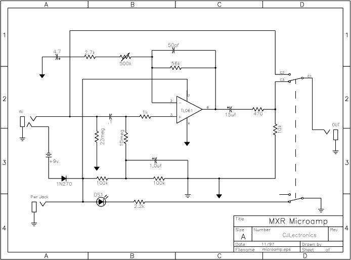
First, we need to trace the circuit, both schematically and physically. The Micro Amp is a well-known circuit, and good schematics exist; I used the Micro Amp schematic from the DIYstompboxes.com schematics page.
Then, we trace the physical circuit itself using a multimeter to check for continuity between points. Find a good continuity checking tutorial and poke around the circuit to confirm your understanding of the schematic.

Click for a larger image.

Click for a larger image.
Notice that there’s circuit traces on both the top and bottom of the board. By studying the schematic and tracing the circuit with my multimeter, the only significant, yet minor difference between the “classic” schematic and the Rev. D printed circuit board is that the LED is wired up as power -> resistor -> switch -> LED -> ground, rather than power -> LED -> resistor -> switch -> ground. Not a difference that matters for this operation. It is also apparent that the contact point for the input signal falls between the input resistor and the input capacitor, requiring me to cut both circuit traces around the input contact, then to jumper the resistor and capacitor contact points together.
Also worth mentioning is that the gridwork on the bottom of the board is a network of traces all connecting to ground. Some of the traces on the board are connected to this gridwork, as opposed to the traces that clearly look like they’re isolated from the gridwork. Still, for the final connection to ground from the 3PDT, I’ll connect to the ground lug on the output jack, rather than some other ground connection on the board.
Here are the critical contact points corresponding to the 3PDT switch wiring:
- Effect input: R1/C1 (in parallel)
- Effect output: R6
- Power: R19
Desoldering
The first step is to desolder the surface-mounted DPDT switch. This was a pain for me, taking a long time, likely because I didn’t have the best tools for the job: a 40w iron with a medium tip, a braid of desoldering wire, and a plastic solder-sucker. I eventually got it out, but it likely would’ve gone much faster if I’d used a pencil-tip and a better solder-sucking tool. Applying a bit of new solder and then sucking everything back out seemed to help. Suffice it to say, MXR pedals are built like little tanks, and parts don’t come off easily.
I also desoldered the critical contact points a bit, in anticipation of applying fresh solder when attaching the wires from the 3PDT. Then I took an X-Acto knife to cut the two traces around the input jack contact, checking with the multimeter that the traces were indeed cut—kinda undoes the whole true bypass operation if they aren’t. Part of the continuity checking at this point required plugging a cable into the input jack, as the input contact is grounded when a cable isn’t plugged in.
Carving
Now for the scary part! Since the 3PDT can’t physically fit where the DPDT was connected, we need to physically carve a chunk out of the circuit board. What complicates this operation for this particular board is that there are small traces on the bottom of the board (connecting the switch from the DC jack that disconnects battery power when using an AC adapter) and the top of the board (connecting the DC jack to the power capacitor, the trace residing under the “R19” label) that we need to take care to leave intact. Well, actually, we can always reconnect these points manually with jumpers if we cut them, but I did my best to avoid having to do so:

Click for a larger image.
Notice the trace under the “R19 label” from the DC jack to the capacitor remains
intact.

Click for a larger image.
Click for a larger image.
Notice the trace from the DC jack switch to the battery circuit remains intact.
Also notice that I’ve already cut the two traces around the input jack contact,
and jumpered the contacts for R1 and C1 together.
I used a Dremel EZ Lock cutting wheel to carve out the board, wearing both protective goggles (which I also use while soldering) and a breath mask to avoid breathing in fiberglass dust. Then I used the multimeter to make sure the contacts I aimed to avoid were indeed preserved.
3PDT insertion
Before installing the new 3PDT switch, I soldered in the jumpers for the input signal and ground connections as illustrated in the above diagram:

Click for a larger image.
Then I put it in the pedal housing, and laid the board on top of it, and…well, first, let me point out another detail I’d missed earlier. This is the view of the installed Micro Amp switch from the side:

Click for a larger image.
Notice the notch in the shaft of the switch. Turns out there’s a corresponding guide tab sticking out from the side of the hole for the switch in the pedal housing, meaning there was effectively only one way to orient the switch, leading to this:

Click for a larger image.
Yeah. Kind of not the ideal fit. The board still rests on top of the switch a little; as I’ll show below, the pedal still fits together despite this. But if it bothered me more than it did, I’d either carve through the power -> capacitor trace on the top of the board and jumper the contacts together, or drill out the guide tab from the switch hole so I can turn the switch however I want.
Finished Project
After getting the 3PDT to fit, wiring the switch to the appropriate contacts was relatively quick and straightforward. In the images below, the green wires lead from the input jack, to the effect input, from the effect output, and to the output jack; the red wires lead from the power and to the LED; and the black wire connects to the ground lug on the output jack.

Click for a larger image.

Click for a larger image.
Notice that the circuit board is tilted a bit due to resting on the 3PDT switch.

Click for a larger image.

Click for a larger image.
Despite the tilt of the circuit board resting on the 3PDT switch, the DC power
jack is still perfectly accessible.

Click for a larger image.
Notice the connection from the switch to the LED is much more visible from this
angle.
Wrapping Up
The end result: Success! The Micro Amp is now perfectly true bypass, powers up and works as-advertised. Though a little funky, the angle of the board resting on the 3PDT doesn’t seem to be hurting anything. If if does somehow break something one day, oh well—time to get a new Micro Amp and repeat the operation. Or, perhaps by the time that day comes, a newer revision of the Micro Amp circuit with true bypass will already have been released!
And how does it sound? Well, just like it did before. Can’t really tell a difference. But now my ideological unrest over having a hardwire bypass pedal in my chain is relieved, and I got to exercise my geek impulses to boot. Totally worth it.
Ah, but there is one final catch: The size and orientation of the 3PDT makes it impossible to fit a 9V battery properly anymore. I have a pedalboard—well, pedalboards—with power supplies (T-Rex Fuel Tank Jr., various Voodoo Lab products), but I still want to be able to tear the Micro Amp and the TU-3 off the board, stick ’em in my gig bag, and plug ’em in at a jam without having to resort to an AC power adapter, such as my 1 Spot. I mean, I’ll do what I have to, but…are there other options?
Turns out there is one especially attractive option, namely building a small, portable, rechargeable 9.6V battery-powered supply that can power several (typical) pedals. The parts are on the way, and when I get around to putting them together, I’ll let you know how it goes!
Footnotes
-
Active pickups, by design, are not impacted by cable length, as they buffer the signal directly from the guitar itself; but they require battery power, and if you like fuzz pedals, particularly Fuzz Faces, they’re likely not for you, as fuzz effects generally interact poorly with buffered signals. Hence the advice to place fuzz pedals before any buffered effects in your chain. ↩
-
User “chervokas” on The Gear Page has frequently explained this phenomenon at length in the “Effects, Pedals, Strings & Things” forum. However, do not follow that link to TGP. If you do, I’m not responsible for time, money, relationships, jobs, livelihoods, hope and sanity lost. ↩
-
“Widely believed” because the current manual doesn’t publish this spec, and neither I nor anyone has actually measured it (or at least published the results). However, the predecessor model, the TU-2, did have a published 1M Ohm input impedance. ↩
-
MXR has a list of true “hardwire” bypass and regular hardwire bypass pedals but it isn’t perfectly up-to-date; I confirmed in an email with a Jim Dunlop tech that my Phase 90 Rev. F is true bypass. Though new MXR pedals have DPDT switches still, they make use of the Millenium circuit to toggle the on/off LED without needing to resort to a 3PDT. This is effectively more reliable and cheaper for mass-produced pedals, as I understand it. ↩